Why Cylinder Selection Is a Cost Decision, Not a Catalog Decision
Most hydraulic cylinder problems are not manufacturing defects. They are specification errors — a cylinder that was the wrong size, the wrong mounting, or the wrong pressure class for the job it was handed. The failure usually shows up months later as a bent rod, a blown seal, a cracked barrel, or a machine that simply cannot lift what it was supposed to lift.
For OEMs, fleet operators, and equipment builders sourcing cylinders, the cost of getting this wrong is threefold: the replacement part, the downtime, and the credibility hit with the end user. A cylinder that costs a few hundred dollars to buy can cost thousands in a failed field test or a warranty claim.
This checklist walks through the eight decisions that determine whether a cylinder will survive its duty cycle. Work through them in order — each one constrains the next.
Step 1: Define the Application and Duty Cycle Before Anything Else
Before you look at a single dimension, answer these questions. They will eliminate half the catalog immediately.
- What is the cylinder doing? Lifting, pushing, pulling, holding, tilting, or positioning.
- What is the load? Static weight, dynamic inertia, or a combination. Include the weight of the linkage, not just the payload.
- How often does it cycle? Cycles per hour, hours per day, days per year. A cylinder that cycles 20 times a day is a different design problem from one that cycles 20 times a minute.
- What is the environment? Outdoor, washdown, abrasive dust, salt spray, high ambient temperature, sub-zero cold start.
- What happens if it fails? Is this a convenience function or a safety-critical one? Safety-critical applications justify a higher specification margin.
- Manual or automated control? Automated systems often need position feedback and tighter seal performance.
Duty cycle is the single most under-specified input in cylinder selection. A cylinder rated for the correct force but selected for light-duty sealing will fail early in a high-cycle application — not because it was too weak, but because the seals and rod surface were never designed for that many strokes.
Step 2: Calculate the Force You Actually Need
Force in a hydraulic cylinder follows a simple relationship:
F = P × A
Where F is force, P is system pressure, and A is the effective piston area. This means you have two levers to pull: raise the pressure, or increase the bore.
In practice, pressure is usually fixed by the rest of the hydraulic system — the pump, valves, and hose ratings. That makes bore the variable you control. And it is rarely a straight calculation, because you must account for:
- Mechanical advantage of the linkage or boom geometry. A cylinder acting at an angle or on a pivoting arm does not deliver its full rated force to the load.
- Safety margin. Industry practice is to size for the working load plus a margin. A cylinder that runs at 100% of its rated capacity on every stroke has no headroom for shock loads.
- Shock and dynamic loads. A load that stops suddenly can produce forces well above its static weight. This is where undersized rods bend.
- Friction. Seal friction, gland friction, and linkage friction all consume force before it reaches the load.
Practical rule: calculate the theoretical force, then verify the cylinder’s rated capacity covers the peak load with margin, not just the steady-state load.
Step 3: Determine Stroke and Collapsed Length
Stroke is determined by the travel your mechanism requires — measured from fully retracted to fully extended, in the actual mounting geometry. Two details trip people up:
- You need the stroke plus the dead length. Collapsed length includes the cylinder’s internal dead length, the rod end, and the mounting hardware. A cylinder that fits at full extension may not fit when retracted, and vice versa.
- Do not run to the mechanical stops. Designing the stroke to end exactly at the cylinder’s internal stop means every cycle slams the piston into the end cap. Leave a small buffer so the cylinder’s own cushioning can do its job.
Step 4: Choose the Mounting Type
Mounting is where geometry and load path meet. It is also where the most expensive mistakes happen, because a mounting that is wrong for the load direction will transfer bending forces into the rod.
| Mounting Type | How It Loads the Cylinder | Typical Applications |
|---|---|---|
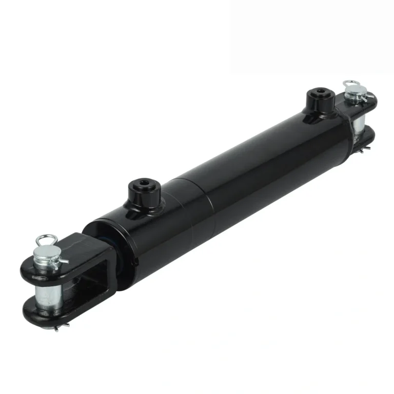
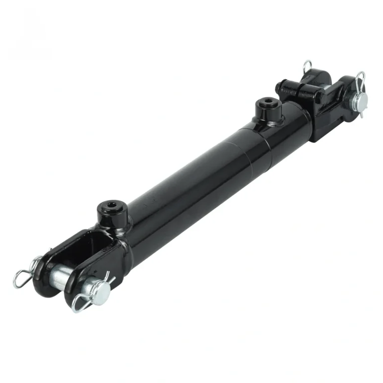
| Clevis (rod end and/or cap end) | Pivoting; handles angular movement | Dump trailers, tipping bodies, linkages |
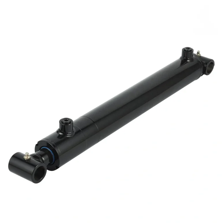
| Cross tube | Pivoting on the tube; compact | Mobile equipment, compact linkages |
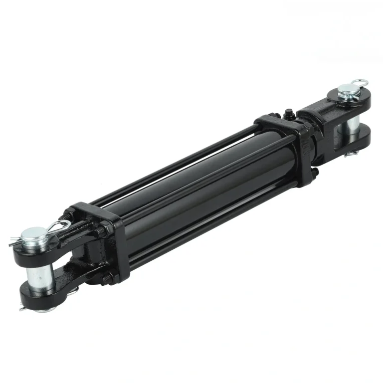
| Tie rod | Straight-line push/pull; versatile | Industrial machinery, presses, general automation |
| Flange / face mount | Rigid; resists side load | Machine tools, presses, fixed installations |
| Trunnion | Pivots mid-body; long strokes | Heavy lifting, large rotating loads |
Two rules to keep in mind. First, match the mounting to the load direction — a cylinder mounted rigidly that is asked to accommodate misalignment will bend its rod. Second, if the linkage has any angular travel, use a pivoting mounting at both ends and check that the pivot geometry does not create a side load at any point in the stroke.
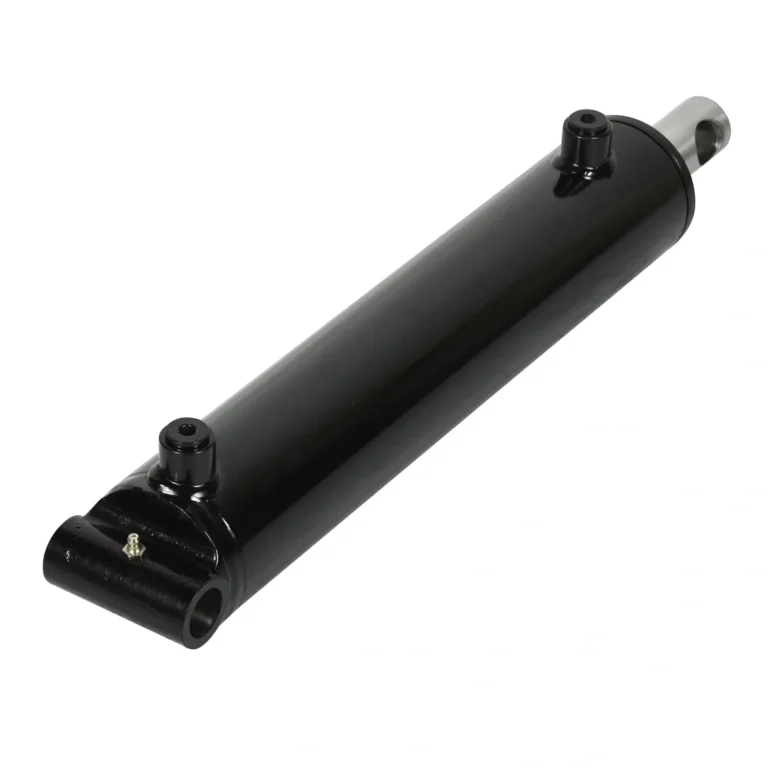
For reference on how these mountings look in finished products, see our range of standard hydraulic cylinders, including clevis-mounted welded cylinders and cross tube mount designs.
Step 5: Select Bore and Rod Diameter
Bore comes from the force calculation in Step 2. Rod diameter is a separate problem, and it is governed mainly by buckling.
A long, pushed rod behaves like a column. If the compressive load exceeds what the column can carry, it buckles — and the failure is sudden, not gradual. Buckling capacity depends on:
- Rod diameter (governs strongly — capacity rises roughly with the fourth power of diameter)
- Effective stroke length (longer stroke means lower buckling capacity)
- Mounting configuration (how the ends are constrained)
Practical rule: when a cylinder must push a heavy load over a long stroke, increase the rod diameter rather than the bore. A larger rod also improves side-load tolerance and reduces the chance of a bent rod in a mobile application.
The retract side deserves attention too. On a double-acting cylinder the effective area on the retract stroke is the piston area minus the rod area. This means a cylinder produces less force retracting than extending — often 20–30% less. If your critical load is on the retract stroke, size for retract, not extend.
Our tie rod cylinders are commonly specified for industrial push/pull duty where straight-line force and easy serviceability matter most.
Step 6: Set the Pressure Rating and Seal Specification
Determine the maximum system pressure the cylinder will see — including pressure spikes, not just the nominal setting of the relief valve. Then specify a cylinder rated above it.
Seal selection follows from three inputs: pressure, temperature, and fluid. The common families are:
- Nitrile (NBR) — general purpose, petroleum-based hydraulic oil, moderate temperatures.
- Polyurethane (PU) — high abrasion resistance and pressure tolerance; common in mobile equipment.
- PTFE-based — high temperature and aggressive fluid compatibility.
- Viton (FKM) — high temperature and chemical resistance.
Seal choice determines the cylinder’s usable temperature window and its compatibility with the fluid in your system. A seal that is correct for mineral oil may fail rapidly with a fire-resistant fluid or a biodegradable ester. Always confirm seal material against the actual fluid, not the fluid category.
Step 7: Specify Materials and Surface Protection
Two surfaces define the cylinder’s service life: the bore, and the rod.
The barrel carries the pressure. Its inner surface is honed to a fine finish so the piston seal can run without tearing. Barrel material and wall thickness determine pressure capacity.
The rod carries the load and takes all the abuse. It needs a hard, corrosion-resistant surface. Chrome plating is the industry standard, with plating thickness and hardness determining how well the rod resists pitting in wet, salty, or chemical environments.
Specify surface protection against the actual environment:
- Standard chrome for general industrial and indoor use.
- Heavier chrome plating or alternative coatings for marine, washdown, and road-salt exposure.
- Painted or coated barrels for outdoor mobile equipment.
For machines that work outdoors year-round — construction equipment, auto haulers, and municipal vehicles — corrosion protection is not cosmetic. A pitted rod destroys seals, and a leaking cylinder contaminates the whole hydraulic system.
Step 8: Decide Whether a Standard Cylinder Fits, or You Need Custom
Standard cylinders are faster to source, cheaper per unit, and easier to replace. They are the right choice when your requirements land inside published ranges for bore, stroke, pressure, and mounting.
Custom manufacturing becomes the better economic choice when:
- The mounting geometry does not exist in any catalog.
- The cylinder must fit a space with hard envelope constraints.
- The application demands a non-standard combination of bore, stroke, and pressure.
- You need specific materials, coatings, or seal compounds for a harsh environment.
- Volume justifies tooling for a purpose-built design.
- An existing machine needs a drop-in replacement for an obsolete part.
For these cases we build cylinders to drawing — see our custom manufacturing capabilities. The relevant question is rarely “can it be made,” but “what documentation does the supplier need to make it right the first time.”
The Specification Mistakes That Cost the Most
- Sizing for steady-state load and ignoring shock. The most common cause of bent rods.
- Under-sizing the rod on a long push stroke. Buckling failure is sudden and total.
- Ignoring the retract-side force. A cylinder can be strong enough to lift and too weak to hold or retract under load.
- Mismatching mounting to load direction. Turns axial force into a bending moment the rod was never designed for.
- Specifying seals without confirming fluid compatibility. Leads to premature seal failure that looks like a quality defect.
- Skipping corrosion specification. The cylinder works perfectly in the workshop and fails in the field.
- No duty-cycle information given to the supplier. Without it, the supplier cannot recommend the right seal class or surface treatment.
What to Send a Supplier for an Accurate Quote
If you want a quote that does not come back with questions, provide:
- Application description and duty cycle (cycles per day, expected service life)
- Required force or load, and pressure available
- Bore, rod diameter, and stroke (or the geometry, if you need help deriving them)
- Mounting type and interface dimensions, or a drawing
- Operating environment and temperature range
- Hydraulic fluid type
- Any required standards, certifications, or test documentation
- Quantity and delivery expectation
Send a drawing where one exists. If none exists, send the machine dimensions and load data — the specification can be derived from them.
Frequently Asked Questions
What size hydraulic cylinder do I need?
Size the bore from the force requirement and the available system pressure, then size the rod for buckling over the full stroke, and confirm the mounting can carry the load direction. Force equals pressure multiplied by effective piston area, so bore and pressure together determine capacity.
How do I calculate hydraulic cylinder force?
Multiply system pressure by the effective piston area. For the extend stroke, use the full bore area. For the retract stroke on a double-acting cylinder, subtract the rod area from the bore area — which is why retract force is always lower than extend force.
Should I choose a standard or custom hydraulic cylinder?
Choose standard if your bore, stroke, pressure, and mounting fall within published ranges and the environment is moderate. Choose custom when mounting geometry, envelope constraints, environmental demands, or replacement of an obsolete part require a purpose-built design.
How much safety margin should a hydraulic cylinder have?
The margin should reflect the application’s shock and dynamic loading. Light-duty positioning can work with a modest margin; mobile equipment, lifting, and safety-critical functions need a larger margin to absorb shock loads that can exceed the static load significantly.
Why do hydraulic cylinder rods bend?
Usually one of three reasons: the rod was undersized for a long push stroke and buckled; the mounting transferred a side load or misalignment into the rod; or a shock load exceeded the calculated working force.
Get the Specification Right the First Time
Sending a correct specification is cheaper than correcting a wrong one. If you are working from a machine drawing, a load requirement, or a failed part you need to replace, send us the details — we will come back with a cylinder specification, not a list of questions.
For standard ranges, browse our hydraulic cylinder product line. For applications that fall outside the catalog, start with custom manufacturing.
Related Technical Guides
- Hydraulic Cylinder Sizing Guide — How to calculate bore from force and size the rod for buckling, with worked examples.
- Single-Acting vs Double-Acting Hydraulic Cylinders — How each type works, force and control differences, and how to choose.
- Hydraulic Cylinder Maintenance Guide — Inspection schedule, seal failure modes, contamination control and troubleshooting.
- How Does a Hydraulic Cylinder Work? — Pascal’s law, internal components and the extend and retract strokes.