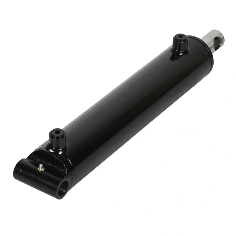
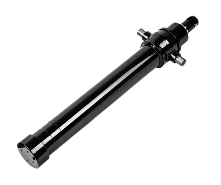
Three Numbers Define Every Hydraulic Cylinder
When an engineer specifies a hydraulic cylinder, the conversation eventually reduces to three numbers: bore, rod diameter, and stroke. Everything else — mounting, seals, coatings, port sizes — follows from those three.
Get them right and the cylinder works for the life of the machine. Get any one of them wrong and you get a failure that looks like a manufacturing problem but is actually a sizing problem: a bent rod, a leaking gland, a machine that moves too slowly, or a load that will not lift.
This guide works through the sizing logic in the order a designer should apply it, with worked numbers so you can follow the arithmetic and apply it to your own application.
Step 1: Size the Bore from Force and Pressure
The governing relationship is simple:
F = P × A
Where F is force, P is pressure, and A is the effective piston area. Since pressure is normally fixed by the hydraulic system, bore is the variable you choose.
The piston area for a given bore is:
A = π/4 × D²
Using practical units, force in kilonewtons comes from pressure in bar and area in square millimetres:
F (kN) = P (bar) × A (mm²) × 0.1 ÷ 1000
The table below shows push force for common bore sizes at three typical system pressures. Use it as a starting point, then confirm against your own pressure.
| Bore (mm) | Piston Area (mm²) | Force @ 160 bar | Force @ 200 bar | Force @ 250 bar |
|---|---|---|---|---|
| 50 | 1,963 | 31.4 kN (3.2 t) | 39.3 kN (4.0 t) | 49.1 kN (5.0 t) |
| 63 | 3,117 | 49.9 kN (5.1 t) | 62.3 kN (6.4 t) | 77.9 kN (7.9 t) |
| 80 | 5,027 | 80.4 kN (8.2 t) | 100.5 kN (10.2 t) | 125.7 kN (12.8 t) |
| 100 | 7,854 | 125.7 kN (12.8 t) | 157.1 kN (16.0 t) | 196.3 kN (20.0 t) |
| 125 | 12,272 | 196.3 kN (20.0 t) | 245.4 kN (25.0 t) | 306.8 kN (31.3 t) |
| 160 | 20,106 | 321.7 kN (32.8 t) | 402.1 kN (41.0 t) | 502.7 kN (51.2 t) |
Tonnes shown are metric tonne-force (1 t = 9.81 kN), for reference only. Always confirm ratings against the cylinder manufacturer’s published data.
Worked example
Suppose your machine needs to lift 8 tonnes (78.5 kN) and the hydraulic system runs at 200 bar. Dividing force by pressure gives the area you need:
78,500 N ÷ (200 bar × 0.1 N/mm² per bar) = 3,925 mm²
The next standard bore above 3,925 mm² is 80 mm (area 5,027 mm²), which delivers 100.5 kN at 200 bar. That is roughly 28% headroom over the required lift — sensible for a static load, but check whether your application has shock or dynamic loading before accepting it.
Step 2: Check the Retract Stroke Separately
On a double-acting cylinder, the rod occupies part of the piston area. During retraction, pressure acts on the annular area only — piston area minus rod area:
Aannulus = π/4 × (D² − d²)
This means retract force is always lower than extend force. How much lower depends on how large the rod is relative to the bore.
| Bore / Rod (mm) | Extend Force @ 200 bar | Retract Force @ 200 bar | Retract as % of Extend |
|---|---|---|---|
| 63 / 36 | 62.3 kN | 42.0 kN | 67% |
| 63 / 45 | 62.3 kN | 30.5 kN | 49% |
| 100 / 56 | 157.1 kN | 107.8 kN | 69% |
| 100 / 70 | 157.1 kN | 80.1 kN | 51% |
| 125 / 70 | 245.4 kN | 168.5 kN | 69% |
The lesson is direct: if your critical load is carried on the retract stroke — a pull, a hold-down, or a return under load — size the cylinder for retract force, not extend. Selecting on extend force alone routinely produces a cylinder that lifts the load but cannot lower it under control.
Step 3: Size the Rod for Buckling, Not Just for Load
Rod diameter is a strength question, but for long push strokes it becomes a stability question. A rod loaded in compression behaves like a column: past a critical load it buckles suddenly, without warning, and the cylinder is destroyed.
The critical buckling load follows the Euler relationship, where capacity falls with the square of the effective length and rises with roughly the fourth power of rod diameter:
Fcr = π² E I / L²
Where E is the modulus of elasticity, I is the second moment of area of the rod section, and L is the effective length — which depends on how the cylinder ends are constrained. A pivoting mounting at both ends gives a longer effective length and therefore lower buckling capacity than a rigidly guided rod.
The table below gives indicative safe compressive loads for steel rods at various strokes, assuming pivoted ends and a safety factor of 3.5.
| Rod Ø (mm) | Stroke 500 mm | Stroke 1,000 mm | Stroke 1,500 mm | Stroke 2,000 mm |
|---|---|---|---|---|
| 36 | 193 kN | 48 kN | 21 kN | 12 kN |
| 45 | 470 kN | 117 kN | 52 kN | 29 kN |
| 56 | 862 kN * | 282 kN | 125 kN | 70 kN |
| 70 | 1,347 kN * | 688 kN | 306 kN | 172 kN |
* At these shorter strokes the rod is limited by the material’s yield strength rather than by buckling, so capacity stops rising as the stroke shortens. Values are indicative and must be confirmed against the manufacturer’s rated column strength for the specific rod material and end conditions.
Two practical conclusions follow. First, doubling the stroke cuts buckling capacity to a quarter — long-stroke push applications need disproportionately larger rods. Second, if the calculated bore gives you an adequate push force but the rod fails the buckling check, increase the rod diameter rather than the bore. A larger rod costs less than a larger cylinder and solves the actual problem.
Rods are rarely the limiting factor in tension. For a typical chrome-plated steel rod, tensile capacity far exceeds the compressive force the cylinder can produce, so the buckling check governs.
Step 4: Determine the Stroke from the Mechanism
Stroke is dictated by the mechanism, not chosen from a list. Measure the actual travel required at the cylinder’s mounting points, in the geometry where it will operate.
Three details to get right:
- Angular movement changes the required stroke. A cylinder driving a pivoting arm does not produce linear travel equal to its stroke at the load. Work from the linkage geometry.
- Leave buffer at both ends. Do not design the mechanism to run into the cylinder’s internal stop. The cushion at the end of stroke exists to decelerate the load — it cannot do that if the mechanism bottoms out before it engages.
- Check the collapsed length, not just the extended length. Envelope constraints usually bite at the retracted position, and collapsed length includes mounting hardware and rod end fittings.
Step 5: Match Speed to Flow
Once bore is fixed, extending speed is a direct function of flow:
Q = A × v
Where Q is flow, A is piston area, and v is the desired speed. A 63 mm bore cylinder (area 31.17 cm²) extending at 0.1 m/s requires:
31.17 cm² × 10 cm/s = 312 cm³/s = 18.7 L/min
This matters because the pump must supply that flow, and the port must pass it without excessive pressure drop. The same cylinder retracting at the same speed needs less flow, because the annular area is smaller — which is why retract speed is higher than extend speed for a given pump output.
If the application needs both high force and high speed, the bore that satisfies the force requirement may demand more flow than the pump can deliver. In that case, consider a smaller bore at higher pressure, or accept a lower speed. Port sizing follows from the flow and should avoid restricting the circuit.
Step 6: Bring It Together — A Complete Sizing Example
Application: a mobile lifting function must raise 6 tonnes (58.9 kN) over a 900 mm stroke, on a system running at 200 bar, with a pivoting mounting at both ends.
- Bore: required area = 58,900 ÷ 20 = 2,945 mm². Next standard bore is 63 mm (3,117 mm²), giving 62.3 kN at 200 bar. A 50 mm bore would give only 39.3 kN — insufficient.
- Rod: with pivoted ends at a 900 mm stroke, the 36 mm rod provides about 48 kN of safe compressive capacity at 1,000 mm — below the 62.3 kN the cylinder can push. Move up to a 45 mm rod, which offers roughly 117 kN at 1,000 mm and clears the requirement with margin.
- Retract check: the 63/45 combination retracts at 30.5 kN. If the return stroke carries the load, this is insufficient and the design needs rethinking — a larger bore, or a different linkage.
- Speed: if the stroke must complete in 9 seconds, required speed is 0.1 m/s, needing about 18.7 L/min. Confirm the pump can supply it.
- Mounting and seals: pivoting mounting both ends suits the geometry; seal compound selected for the ambient temperature range and the fluid in use.
The result is a 63 mm bore, 45 mm rod, 900 mm stroke cylinder at 200 bar. Note what happened at step 2 — the bore was set by force, but the rod was set by buckling, and the two decisions were made against different criteria.
Common Sizing Errors
- Selecting the bore from extend force only. The retract stroke may be the critical one.
- Ignoring buckling on long strokes. The single most common cause of bent rods.
- Using peak system pressure without allowing for spikes. Relief valve settings do not capture the transient pressures from decelerating loads.
- Specifying a stroke that runs to the mechanical stop. Every cycle impacts the end cap; cushioning never engages.
- Designing the mounting after the cylinder is chosen. Mounting geometry determines side loads and effective buckling length — it belongs at the start of the process.
- Forgetting flow. A correctly sized cylinder that moves too slowly is still a failed design.
Frequently Asked Questions
How do I calculate hydraulic cylinder bore size?
Divide the required force by the system pressure to get the minimum piston area, then convert that area to a diameter and round up to the nearest standard bore. Force equals pressure times piston area, so bore and pressure together determine the cylinder’s capacity.
What is the difference between bore and rod diameter?
Bore is the inside diameter of the barrel and determines force capacity. Rod diameter is the diameter of the piston rod and determines buckling resistance and side-load tolerance, particularly on long push strokes. Bore is sized from force; rod is sized from stability.
How is hydraulic cylinder stroke determined?
Stroke is the linear travel the mechanism requires, measured at the cylinder mounting points in the operating geometry. It should include a small buffer so the cylinder does not run against its internal stop, and the collapsed length must be checked against the available space.
Why is retract force lower than extend force?
On the retract stroke, pressure acts on the annular area — piston area minus rod area. A larger rod reduces that area further, so retract force is always lower than extend force, sometimes by as much as half.
Why do long-stroke hydraulic cylinders need larger rods?
Because buckling capacity falls with the square of effective length. Doubling the stroke reduces the rod’s safe compressive load to roughly a quarter, so long-stroke push applications require a disproportionately larger rod.
Need the Numbers Checked?
Sizing errors surface as bent rods, slow movements, and failed lifts. If you have a load, a stroke, and an available pressure, send them over — we will come back with a bore and rod recommendation rather than a list of questions. Browse standard hydraulic cylinders for catalog ranges, or see custom manufacturing for non-standard envelopes and mounting geometries.
Related Technical Guides
- How to Choose the Right Hydraulic Cylinder — A buyer’s checklist for specifying load, force, bore, rod, mounting and seals.
- Single-Acting vs Double-Acting Hydraulic Cylinders — How each type works, force and control differences, and how to choose.
- How Does a Hydraulic Cylinder Work? — Pascal’s law, internal components and the extend and retract strokes.